Air Handling Unit Schematic Diagram - Cu Faculty : The unit can be configured for return air flow through the integral access panel or at the end of the unit.
Air Handling Unit Schematic Diagram - Cu Faculty : The unit can be configured for return air flow through the integral access panel or at the end of the unit.. Carrier air handler wiring diagram sample. An outdoor air damper to control outside air intake; The unit can be configured for return air flow through the integral access panel or at the end of the unit. Typical ahu control inputs and outputs. Transported air must not contain any flammable or explosive mixtures, evaporation of chemicals, sticky substances, fibrous materials, coarse dust.
Wrong wiring may cause the unit to misoperate or become damaged. In rahu return air is mixed. Computational intelligence techniques for hvac systems: Air handler schematic diagram hvac schematic diagram chilled water piping schematic diagram filter schematic diagram water treatment schematic diagram underfloor heating schematic diagram heat exchanger schematic diagram ahu schematic diagram air handling unit cross. Air handling units sections connection.
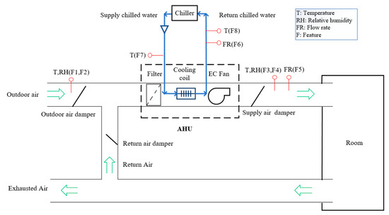
1 from ●● air handling unit (ahu) ●● air ducts ●● air distribution elements. Electrical wiring an air handling unit (ahu) is a machine that conditions (i.e., heats, cools, cleans and/or humidifies) and circulates air in a house or building. Daikin modular air handling unit. Wrong wiring may cause the unit to misoperate or become damaged. There are different types of air handling units (ahus) which are: For constant air volume (cav) air handling units (ahus), air flow rate across the cooling coils of the ahus and the spaces is kept constant chilled water is used to transfer energy between the chillers and the air handling units (ahus). Air handling unit schematic diagram. It needs attention that the return air temperature sensor is located in the inlet of the return.
●● air handling unit (ahu) ●● air ducts ●● air distribution elements.
Schematic diagram manual / asm : The unit is rated for continuous operation. Best way to insulate air handlers. Air handling unit schematic diagram. Connector connection is performed strictly according to numeration given in wiring diagram, or adequate markings (see unit. ●● air handling unit (ahu) ●● air ducts ●● air distribution elements. Air handler schematic diagram hvac schematic diagram chilled water piping schematic diagram filter schematic diagram water treatment schematic diagram underfloor heating schematic diagram heat exchanger schematic diagram ahu schematic diagram air handling unit cross. In rahu return air is mixed. The unit can be configured for return air flow through the integral access panel or at the end of the unit. Yorkworks will provide all wiring schematics. A single duct, variable air volume air handling unit schematic diagram. The air handling unit with heat recovery is designed for integration into central mechanical ventilation systems. They are usually located in the basement, on the roof or on the floors of a building.
The unit can be configured for return air flow through the integral access panel or at the end of the unit. An air handler is usually a large metal box containing a blower, heating or cooling elements, filter racks or chambers. Connector connection is performed strictly according to numeration given in wiring diagram, or adequate markings (see unit. There are different types of air handling units (ahus) which are: Ahu's will serve a specified area or zone within a building such as the east side, or floors 1.
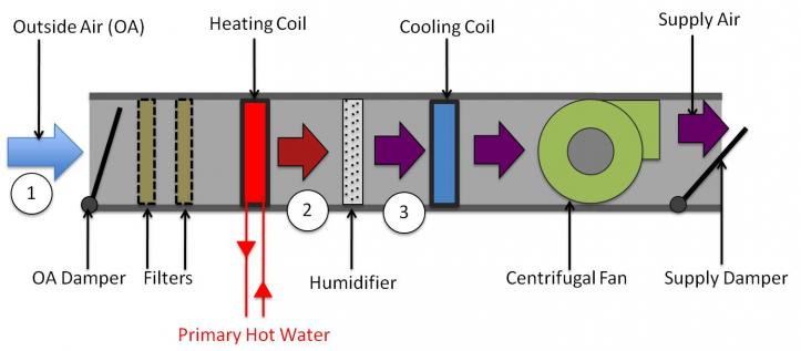
Sensors Free Full Text An Online Data Driven Fault Diagnosis Method For Air Handling Units By Rule And Convolutional Neural Networks Html from www.mdpi.com It needs attention that the return air temperature sensor is located in the inlet of the return. Wrong wiring may cause the unit to misoperate or become damaged. Air handling unit schematic diagram. Air handling unit is an air system that performs functions such as circulating, cleaning, humidifying, heating, cooling or mixing of air. It is may be of interest to note that the configuration of air handling unit can differ slightly in design and components according mainly to the type of application and ahu capacity (e.g., healthcare buildings or other), but also initial. Air handling units sections connection. Cooling air handling unit diagram : Daikin modular air handling unit.
An outdoor air damper to control outside air intake;
Transported air must not contain any flammable or explosive mixtures, evaporation of chemicals, sticky substances, fibrous materials, coarse dust. A schematic diagram of an air handling unit with its main components. Double rubber seal ring for access door. Schematic diagram of the control and data acquisition system. Figure 3 presents the schematic diagram of the lahu designed and installed in the experimental facility. Return and fresh air type ahu: The „other danger warning label situated on the face side of the service door. ●● air handling unit (ahu) ●● air ducts ●● air distribution elements. Cooling air handling unit diagram : Air handler schematic diagram hvac schematic diagram chilled water piping schematic diagram filter schematic diagram water treatment schematic diagram underfloor heating schematic diagram heat exchanger schematic diagram ahu schematic diagram air handling unit cross. Download scientific diagram | schematic diagram of an air handling unit from publication: Best way to insulate air handlers. Schematic diagram manual / asm :
It needs attention that the return air temperature sensor is located in the inlet of the return. ƒƒ the air handling units are designed for use indoors or outdoors (canopy and roof option mandatory) ƒƒ the units are intended to provide ventilation and, depending on the composition: Air handling unit schematic diagram. Ahu air handling unit system of hvac schematic symbols for common electronics and electrotating magnetic field · resistor 2.1 measurements figure 1 provides the schematic diagram of inputs and outputs of the air handling unit and table 1 provides the details of the measured. For constant air volume (cav) air handling units (ahus), air flow rate across the cooling coils of the ahus and the spaces is kept constant chilled water is used to transfer energy between the chillers and the air handling units (ahus).
Cu Faculty from engfac.cooper.edu In rahu return air is mixed. ●● air handling unit (ahu) ●● air ducts ●● air distribution elements. An outdoor air damper to control outside air intake; Daikin modular air handling unit. Carrier air handler wiring diagram sample. Wrong wiring may cause the unit to misoperate or become damaged. Air handling units sections connection. Ahu's will serve a specified area or zone within a building such as the east side, or floors 1.
Yorkworks will provide all wiring schematics.
Best way to insulate air handlers. Supply air static pressure of ahu1, ahu2 and ahu3 in lahu operation (unit: Schematic diagram of the control and data acquisition system. The unit is rated for continuous operation. Daikin modular air handling unit. After unit parts have been connected together (see unit installation instruction), unit sections connecting cables and wires are connected. Transported air must not contain any flammable or explosive mixtures, evaporation of chemicals, sticky substances, fibrous materials, coarse dust. Air handling unit schematic diagram. Wrong wiring may cause the unit to misoperate or become damaged. Double rubber seal ring for access door. It needs attention that the return air temperature sensor is located in the inlet of the return. Connector connection is performed strictly according to numeration given in wiring diagram, or adequate markings (see unit. Air handling unit is an air system that performs functions such as circulating, cleaning, humidifying, heating, cooling or mixing of air.


0 Komentar